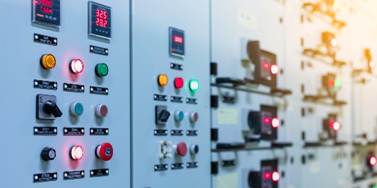
Motor control gear products constitute a substantial part of our offering here at
LED Controls, and are widely used for various purposes in a broad range of industries. For example, they’re often used in conjunction with programmable logic controllers for factory automation in the industrial sector. Below, we cover all the essentials you’ll need to know about motor control gears, including what they are, how they work, and what sort of specific applications they’re often used for.
What is a motor control gear?
Essentially, motor control gear is collective term for electrical disconnect switches, fuses, and circuit breakers, all of which work to control, protect and isolate electrical equipment.
The main functions of motor control gears generally include
• Providing adequate protection to the motor under all conditions
• Facilitating increases or decreases in speed
• Providing a means of braking the motor if necessary
• Giving operators the means of changing the direction of rotation when required
Motor control gears are highly versatile, and they’re used as core components of a vast array of different types of electrical circuits. This includes commercial processes such as factory automation (as we’ve already touched on above), but also extends to domestic appliances and systems.
Some common examples of their use include garage door openers, electric alarm clocks, and the control knobs on washing machines. Hospital beds, commercial jacks, and even full-sized cranes make up some of the most significant commercial applications.
Individual motor control gears can vary in terms of their level of sophistication and specialisation. One of the most simple and common forms of motor control gear is what’s called a Direct On-Line Starter. This comprises a switching device (or contactor), and tripping device (such as an overload relay), all contained within a specialised enclosure.
How does a motor control gear work?
The motor control gear’s primary function is to reduce the level of speed in a gear series, which effectively creates more torque.
To do this, the motor rotor and main shaft is connected to the gear box (or integrated gear series) using a second reduction shaft. This forms what’s commonly referred to as a reduction gear series, or reduction gears train. In theory, this reduction gears train can be extended for as long as required, and the longer it gets, the lower the final output it produces.
A prime example of the motor control gear principle can be found in almost every room, in the form of the common electric clock. The average clock utilises a synchronised AC motor, which spins at about 1500 revolutions per minute (RPM). A reduction gears train is used to decelerate the speed of both the minute and hour hands to the appropriate speeds. This enables the clock to accurately track all three units of time, and ultimately tell you exactly how late or early in the day it is. Without this reduction gear series, the hands would all be moving at the same speed, which obviously wouldn’t be very helpful in telling you whether you’re late for work or not!
The reduction gear train’s ability to generate more torque also makes it invaluable for generating high quantities of force on an object. This force amplification is the basis for many of its industrial and commercial applications, such as the car jacks and cranes we mentioned above.
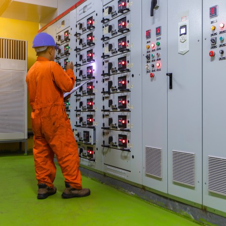
What is a Direct On-Line (DOL) starter?
Most basic control gears are DOL starters. A direct on-line starter is the simplest type of motor starter for large electric motors. It connects directly to the power supply, and instantaneously applies full line voltage, which immediately brings the motor up to full speed.
Unlike a soft starter, which is designed to apply the load more slowly and gradually, a DOL starter generally acts as a stop / start switch for a motor. DOL starters are often fitted with overload devices to mitigate for the increased risk of short circuits, or overheating of the motor.
What is a contactor, or switching device?
A contactor is a relay designed to switch a large amount of electrical power through its contacts. Essentially, it’s a switch that allows you to control a high voltage circuit with a low voltage control circuit.
This is important because if (for example) you have a large machine that requires a high voltage power supply, for safety reasons you won’t want the off button to be wired directly into that high voltage circuit. Low voltage control circuits provide the easiest and safest means to control high voltage power circuits, providing unfettered control over the equipment while posing minimum risk to operators.
Contactors are capable of functioning alone as a power control device, or as a key component of a starter motor. They can be designed to operate at similar voltages to the devices they actually control, or alternatively they can be roughly matched to the voltages of their own control devices.
Contactors are similar in some ways to standard relays, but crucially, they’re designed to connect to high-current load devices, typically within commercial and industrial processes.
What is an overload relay?
An overload relay is first and foremost a protective device - its job is to constantly monitor the amount of current flowing through the motor, and cut the power if this current rises to unsafe levels. Magnetic and electronic overload relays do this instantly, whereas thermal relays cut the power after a certain period of time has elapsed. (We’ll go into the differences between the various different types of overload relays in a bit more detail in just a moment.)
Each overload relay is wired in series with the motor, so that any current flowing to the motor when it’s active will also flow through the overload relay. When the relay detects that there is excess current running through the motor, it will trip by opening its normally-closed contacts. This opens the circuit between the motor and the power source, powering down the motor and thereby preventing the risk of damage to the components, or even a potential threat to human health and safety. Depending on the circuit, the overload relay can be reset manually, or may automatically reset itself after a predetermined period of time.
Thermal overload relays are the most common type of overload relay. These don’t cut off the power instantaneously, as they work by continuously measure a motor’s heating profile, monitoring for signs of a thermal overload. When the motor’s temperature has risen to unsafe levels for a prolonged period of time, the overload relay will trip by using a bimetallic strip to mechanically open the contacts, cutting off the power.
Magnetic overload relays are typically employed in systems and processes where the consequences of overloading can be particularly severe, and therefore tripping needs to be almost instantaneous to avoid extensive damage to components (or even physical danger to human operators). As the name suggests, these types of relays use a magnetic element - when a high enough current passes through this element, it becomes highly magnetised and ultimately pulled out of position, disrupting the circuit and effectively cutting off power to the motor.
Electronic overload relays are microprocessor-based devices or numeric relays based on digital technology. These also use temperature sensors to monitor for excess current passing through the motor. Because of their digital nature, they’re even more precise than thermal relays.
So those are the key essentials of motor control gears - if you’ve got any further questions or need any specialist advice, don’t hesitate to ask us! With 20 years of experience in the motor control equipment industry, we’re able to offer an unrivalled service and wide range of motor control gear products and accessories right here at LED Controls. We stock products from a number of leading brands including ABB, Chint and IMO.
If you have any questions or queries about our services or products here at LED Controls, don’t hesitate to get in touch with the team by emailing
sales@ledcontrols.co.uk. Alternatively, you can give us a call on 08450 756230, or fill in our
contact form.
